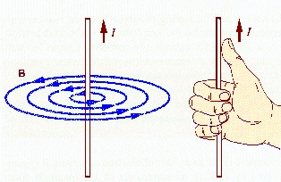
Magnetic Field of a Straight Conductor
A point P is located at a perpendicular distance $d$ from a straight wire carrying current $I$. The wire is finite and $\theta_1$ and $\theta_2$ are the angles as shown in the figure. The magnetic field at the point P is given by
\begin{align} B_P=\frac{\mu_0 I}{4\pi d}(\cos\theta_1-\cos\theta_2) \end{align}The magnetic field at a distance $d$ from an infinitely long straight wire ($\theta_1=0^\circ, \theta_2=180^\circ$) is given by \begin{align} B_P=\frac{\mu_0 I}{2\pi d}. \end{align}
The magnetic field due to a straight current carrying conductor varies inversely with the perpendicular distance $d$ of the point from the conductor. Its magnitude is same at all points at the same distance from the conductor. The magnetic lines of force are circles in planes perpendiculr to the conductor with their centres on the wire.

The magnetic field at a distance $d$ from one end of a semi-infinite straight wire ($\theta_1=0^\circ, \theta_2=90^\circ$) is given by
\begin{align} B_P=\frac{\mu_0 I}{4\pi d}. \end{align}Problems from IIT JEE
Problem (IIT JEE 2000): An infinitely long conductor PQR is bent to form a right angle as shown in figure. A current $I$ flows through PQR. The magnetic field due to this current at the point M is $B_1$. Now, another infinitely long straight conductor QS is connected at Q, so that current is $I/2$ in QR as well as in QS, the current in PQ remaining unchanged. The magnetic field at M is now $B_2$. The ratio $B_1/B_2$ is given by
- 1/2
- 1
- 2/3
- 2
Solution: The magnetic field at the point P (see figure) by a current carrying wire is given by \begin{alignat}{2} &B=\frac{\mu_0I}{4\pi d}(\cos\theta_1-\cos\theta_2).\nonumber \end{alignat}
In first case, the field at the point M by part PQ, part QR, and total field are given by \begin{align} B_\text{PQ}&=\frac{\mu_0I}{4\pi d}(\cos 0-\cos 90)\nonumber\\ &=\frac{\mu_0I}{4\pi d} \end{align} \begin{align} B_\text{QR}&=\frac{\mu_0I}{4\pi d}(\cos 180-\cos 180)=0,\nonumber\\ &B_1=B_\text{PQ}+B_\text{QR}=\frac{\mu_0I}{4\pi d}. \nonumber \end{align} In second case, the field at M by part PQ and part QR remains same as in first case. The field by part QS and total field are given by, \begin{align} B_\text{QS}&=\frac{\mu_0(I/2)}{4\pi d}(\cos90-\cos 180)\nonumber\\ &=\frac{\mu_0I}{8\pi d}, \nonumber \\ B_2&=B_\text{PQ}+B_\text{QR}+B_\text{QS}\nonumber\\ &=\frac{3}{2}\frac{\mu_0I}{4\pi d}. \nonumber \end{align}
Experimental demo
The direction of magnetic field due to a long straight wire is circumferential. The magnetic lines of forces are concentric circles in a plane perpendicular to the wire.
Fix a long stiff wire AB upright in a piece of cardboard kept horizontally. Connect the wire to a battery through a switch, as shown in figure. Use long connecting wires to keep the battery and the switch away from the cardboard. Now, place a compass on the cardboard. Start the current by closing the switch. The compass needle will get deflected, and its direction will show the direction of the magnetic field at that point.
Mark the position of the north pole of the needle on the cardboard. Shift the compass ahead so that south pole of the needle lies at the point marked for the previous position of the north pole. Mark the new position of the north pole. Repeat the procedure till you reach the point from where you started. Join all the points by a smooth curve to give a field line. Similarly, draw other field lines at different distances from the wire. Draw arrows on the lines to show the direction of the magnetic field. If the current is strong, say about 2 A, the lines will be nearly circular. If the current is weak, it will produce a weak magnetic field. Then the earth's magnetic field will have greater effect on the field lines, and they will not be circular.
If the direction of the current is reversed, the field lines will still be circular, but the directions of the field lines will be reversed. This means, the north pole of the needle will point in the opposite direction.
You can also sprinkle some iron filings on the cardboard to see how the field lines are arranged. While a current is passing through the wire, gently tap the cardboard. The iron fillings will get arranged in concentric circles, suggesting that the field lines due to a current passing through a straight wire are circular.
Related
Subscribe to our channel
